- 50mm
- 65mm
- 75mm
- 100mm
- 125mm
- 150mm
- 200mm
- ・8-bit telegram output
- ・Pulse output 100L/P(50 to 125mm)
1,000L/P (50 to 200mm) - ・Systematized maesuring instrument signal
R3212 (100L/P)
R3213 (1,000L/P)
- Standard Functions
-
- Load survey
- Instantaneous flow rate display
- Low battery voltage warning
- False count prevention
- Option
-
- Leakage warning
- Excessive flow warning
- Reverse flow detection
- Water non-use detection
- Excess flow detection
- Regular meter reading
- Terminal call
Features
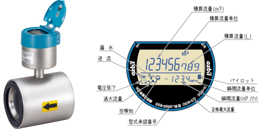
Large, easy-to-read LCD display
Twice as much as conventional
No matter what direction the installation is facing, the 330° rotation allows it to face forward anytime, anywhere. With conventional models, even if there is no problem with the installation direction, it may be difficult to see the display depending on the direction of the lid. In such cases, the display can be easily rotated with one hand in a direction that is easy to see, "no blind spots for meter reading.
- Large, easy-to-read 9-digit totalizer display
- Instantaneous flow rate is also displayed at all times
- Empty detection alarm when water is not full
Alarm display: Notifies abnormal metering by displaying alarms for backflow, empty detection, leakage, battery voltage, excessive flow, etc.
Equipped with backlight function
- Backlight function for easy meter reading in dark places such as buried pits.
- The backlight illuminates for 30 seconds when the lid is opened.
*The backlight turns on for a total of 1 minute per day.
Display rotates 180 degrees.
- This is effective when the display is difficult to read due to installation conditions.
- In the case of vertical piping, the upside-down display is eliminated!
- Easy meter reading.
Other Functions and Features
Approx. 1/10 of conventional models (mass)
- Lightweight and compact
- Built-in battery life of 9 years
- Can be installed in vertical piping
A wide variety of accessories for worry-free replacement!
- Supplemental pipes and spacers are available to match the face-to face dimensions of existing impeller-type water meters, allowing for worry-free replacement installation.
Option
Pulse and telegram output *available
- Easily connectable to a separate measurement indicator (model eKICL) to easily realize a separate measurement display.
- Pulse output to various control devices is possible.
Model : MGB12A
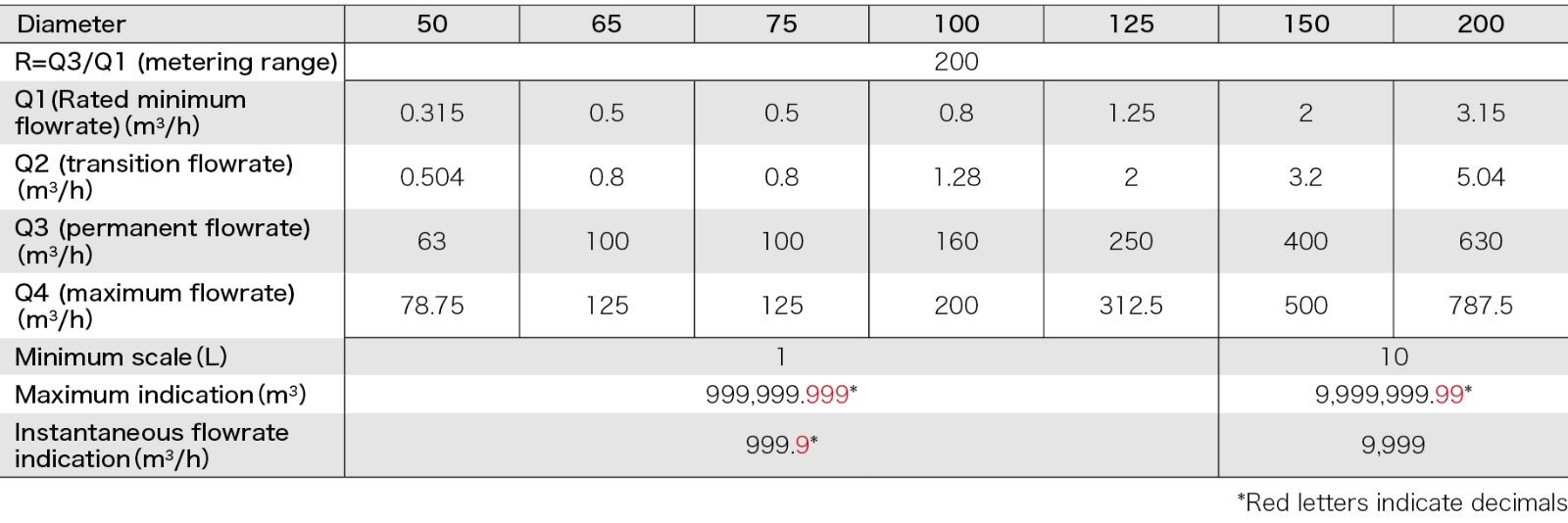
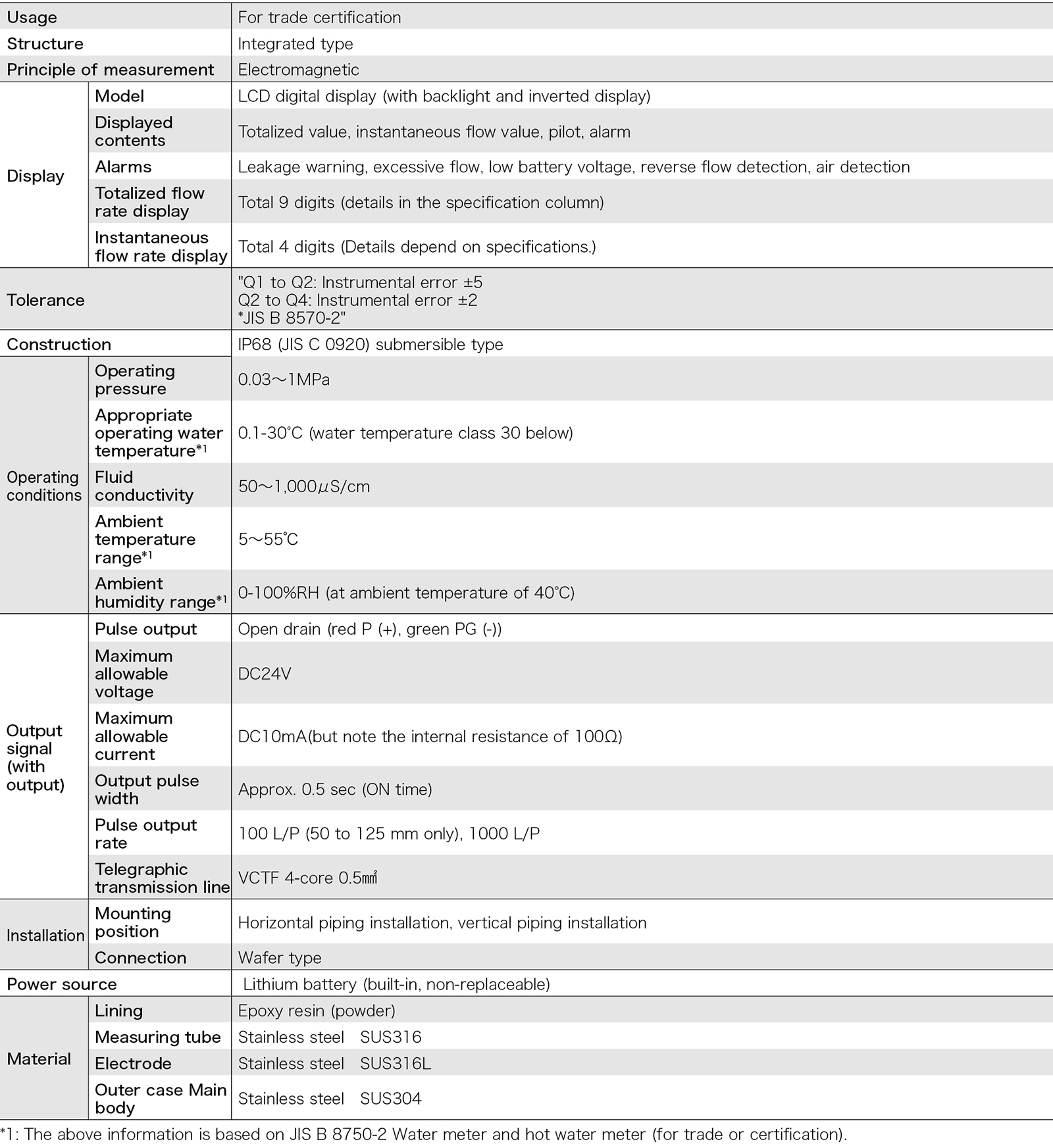
Specification
Approximate ㎥ of usage volume
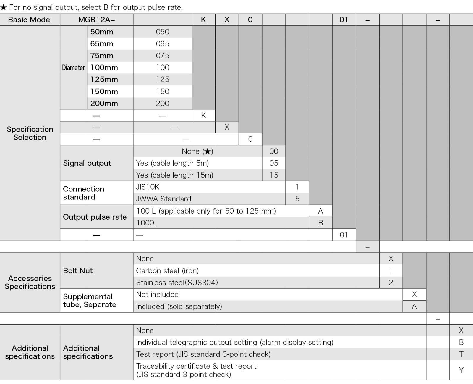
Model Number Table
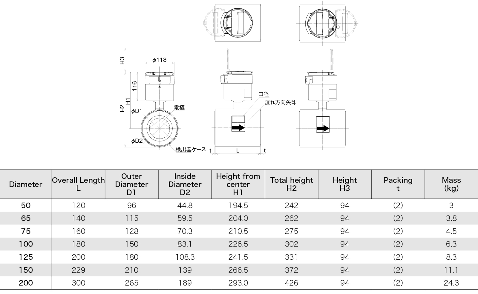
MGB12A main unit
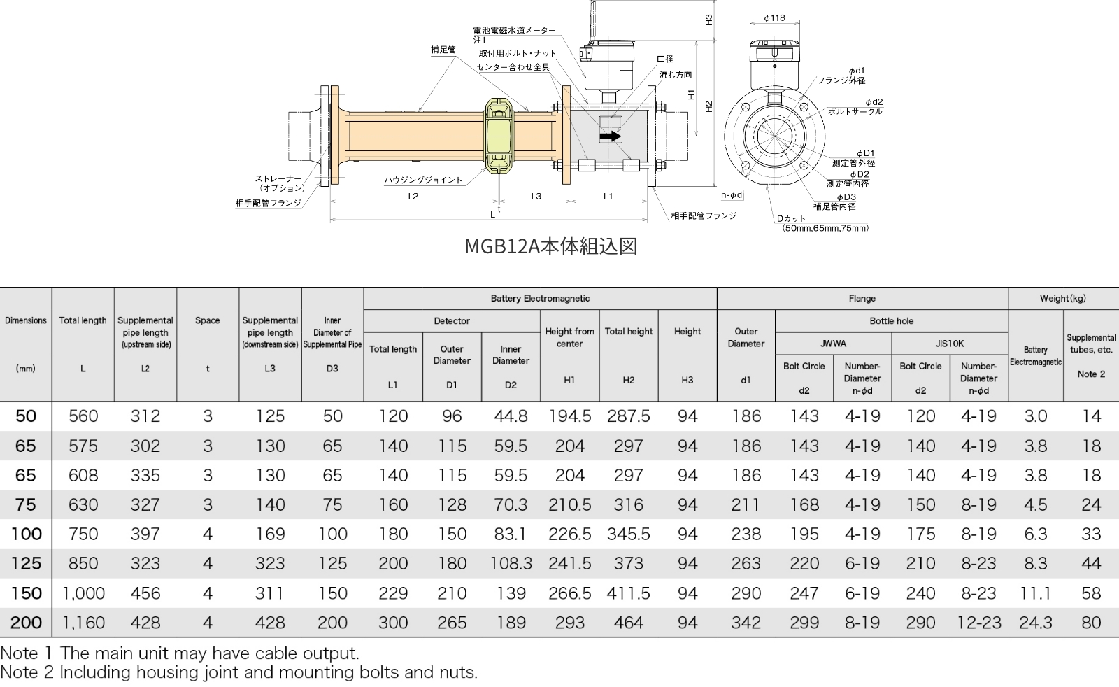
Main Dimensions and External Dimensions
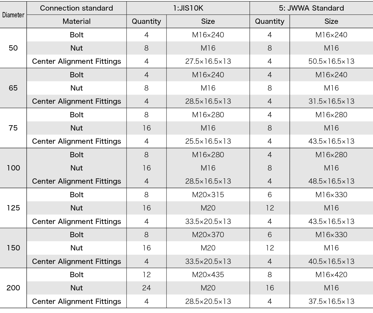
Accessories Pinching connection type
(standard supplemental tube)
External Dimensions
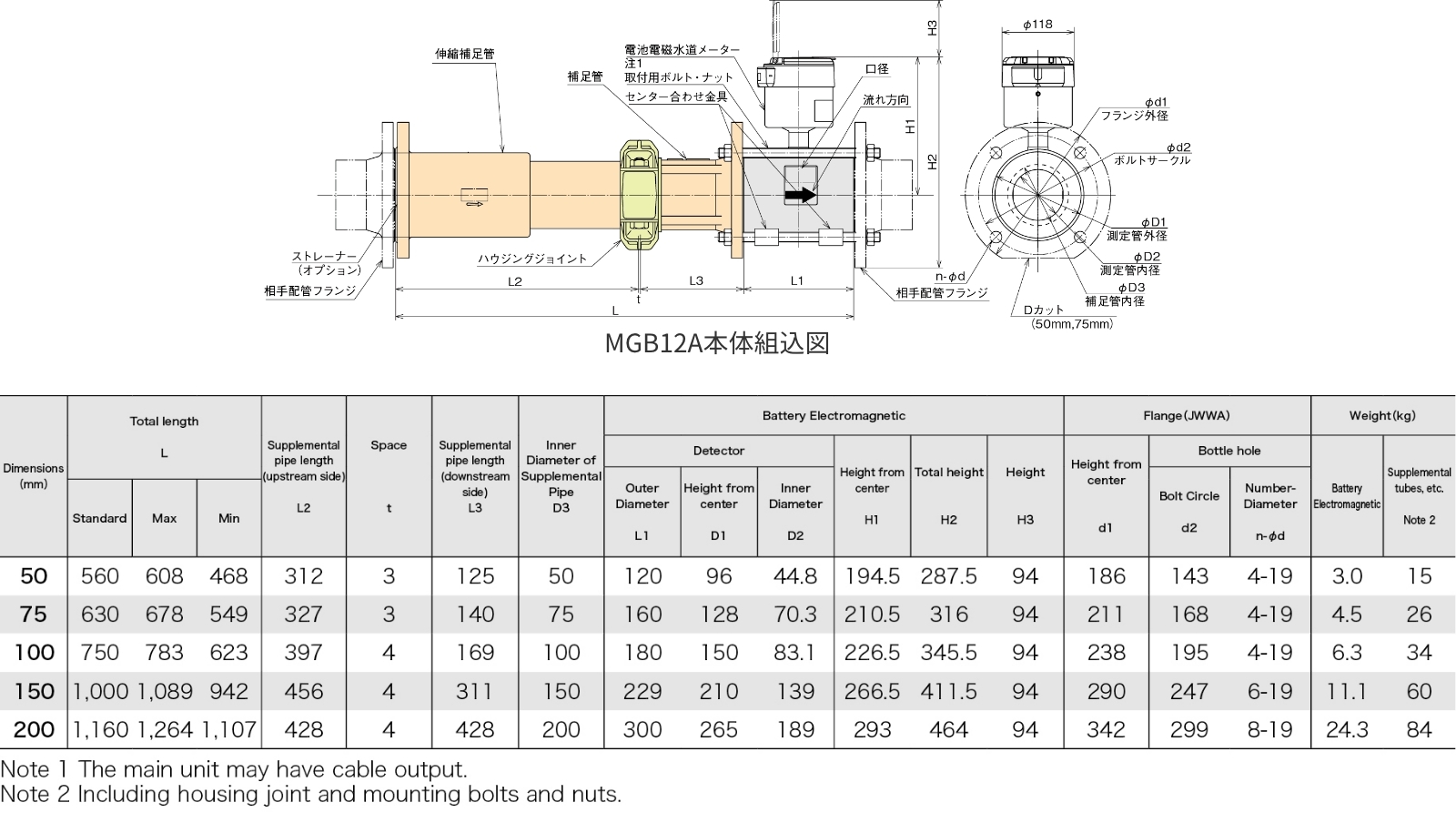
Accessories Pinched connection type
(telescopic supplementary tube)
Main Dimensions and External Dimensions
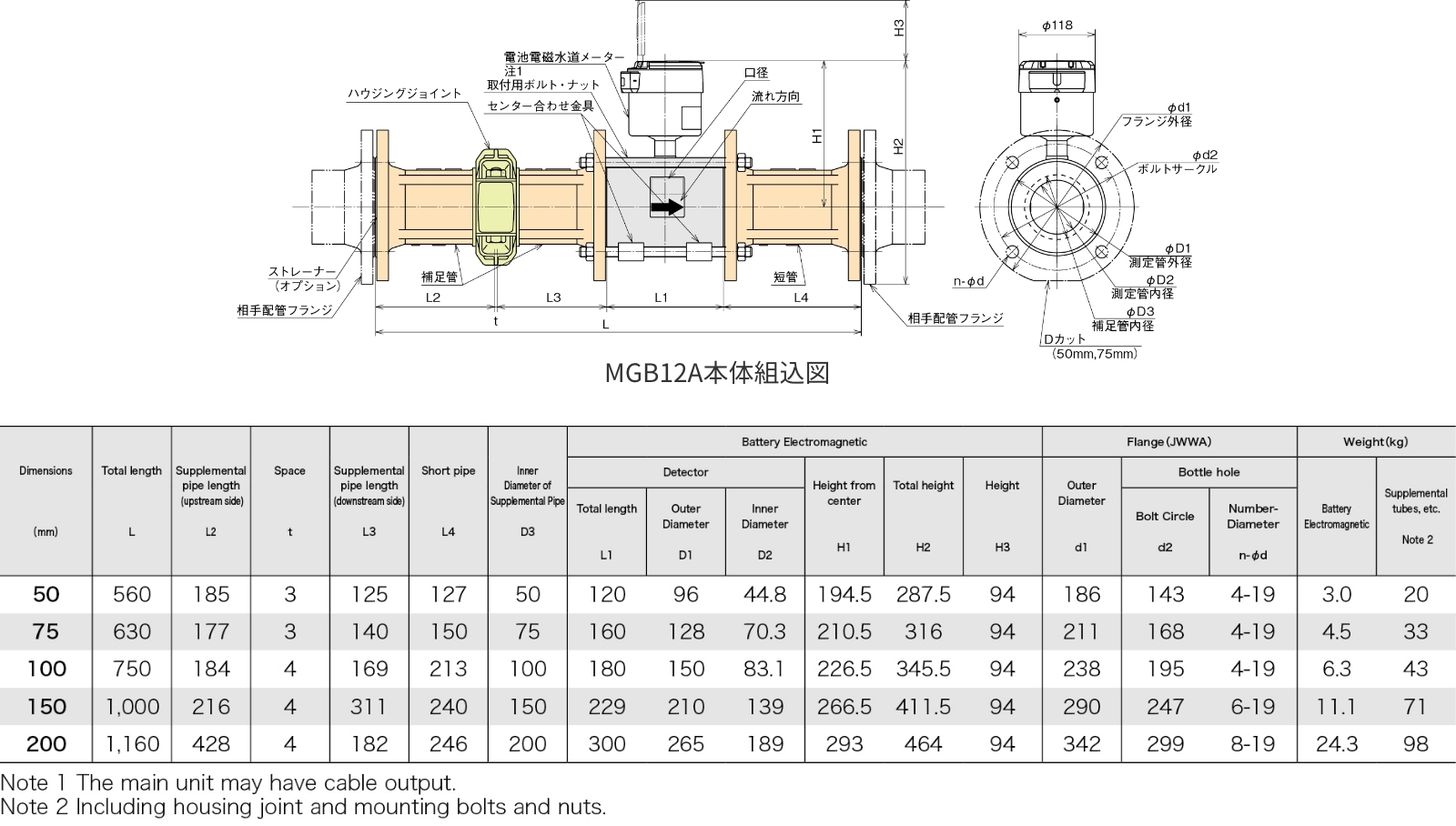
Accessories Flange connection type
Main Dimensions and External Dimensions
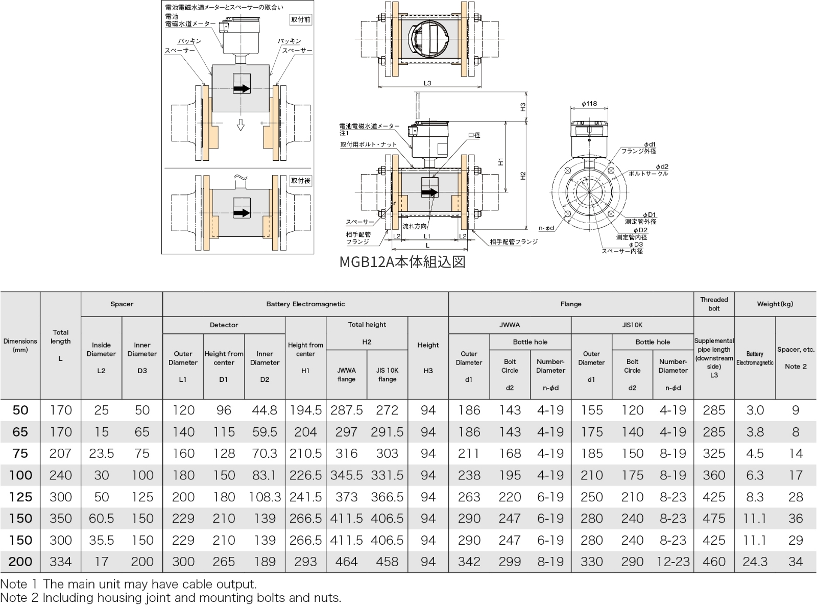
Accessories Spacer connection type
(for TB and WX)
Main Dimensions and External Dimensions
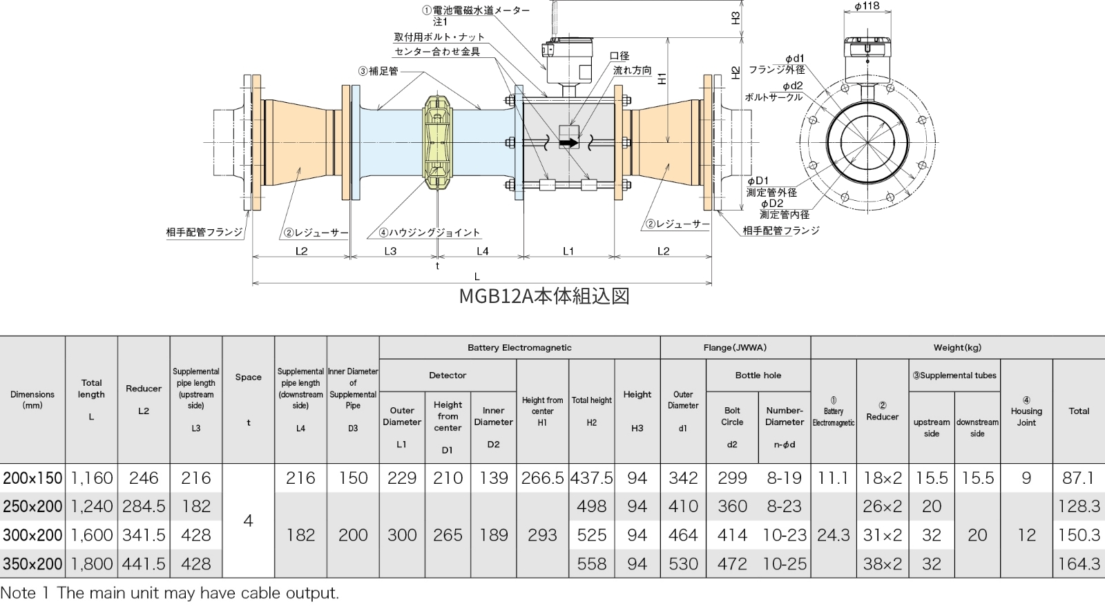
Accessories Reducer connection type
Main dimensions and external dimensional drawings
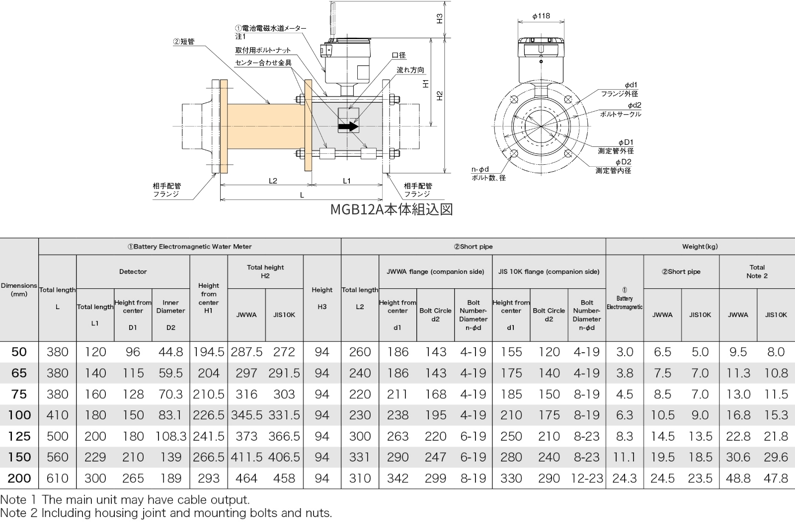
Accessories Short Tube Type for SW
Main Dimensions and External Dimensions
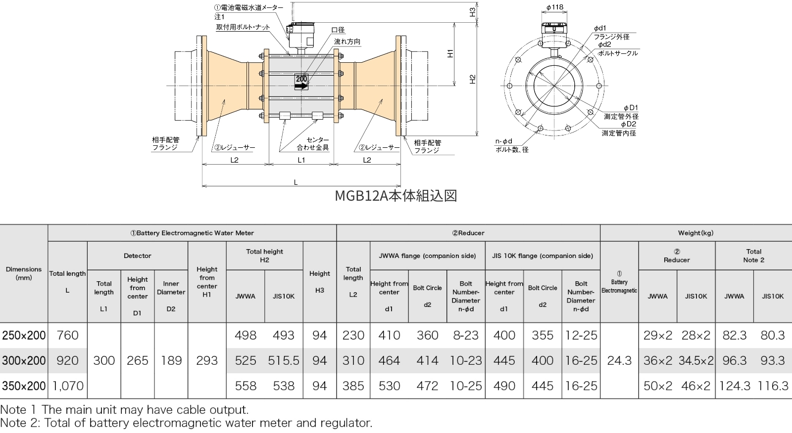
Accessories Reducer connection type for SW
Main Dimensions and External Dimensions
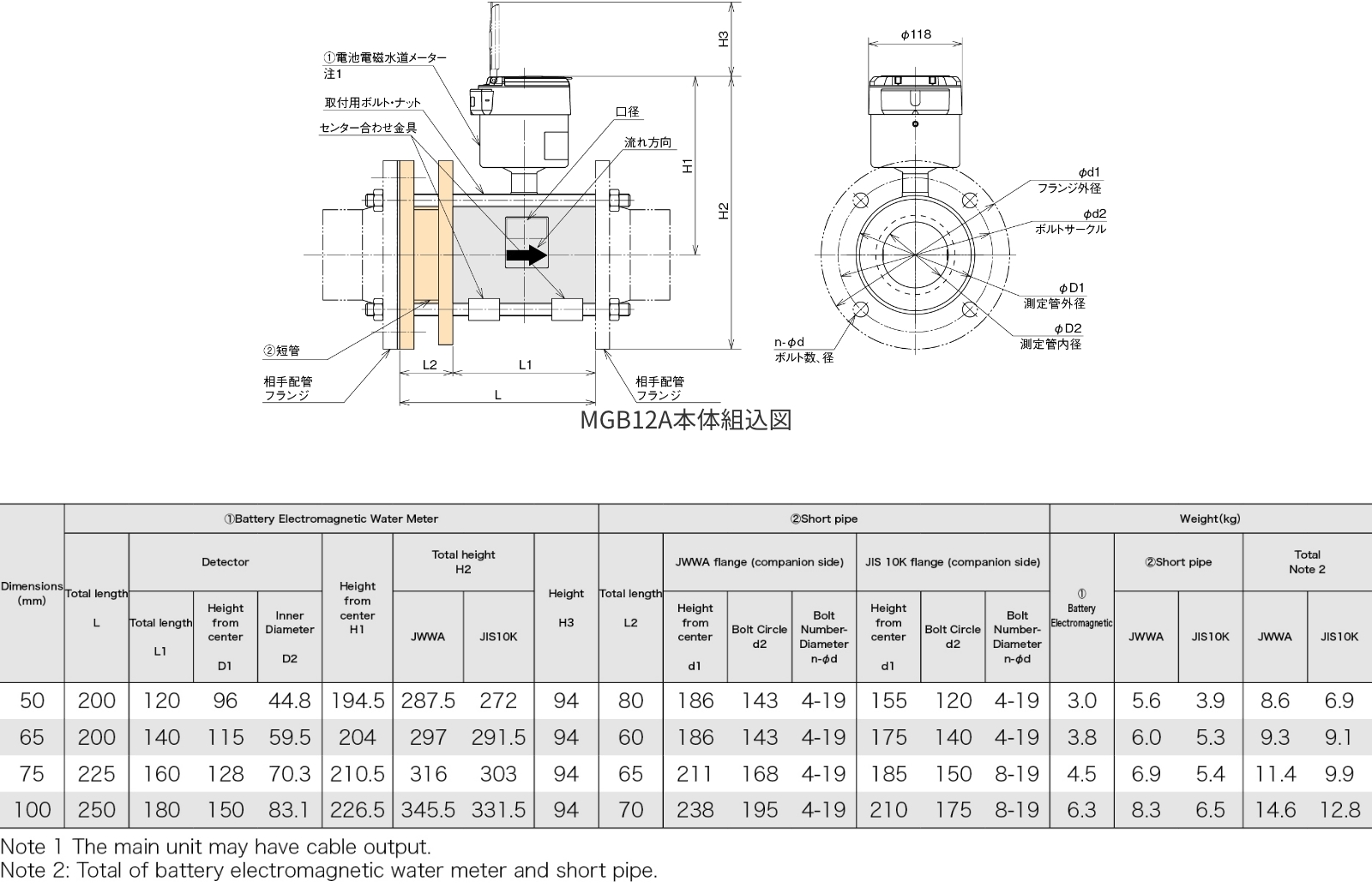
Accessories Spacer connection type
(other special short pipes)
Main Dimensions and External Dimensions
MGB Accessory Dimensions List
Before attaching to piping
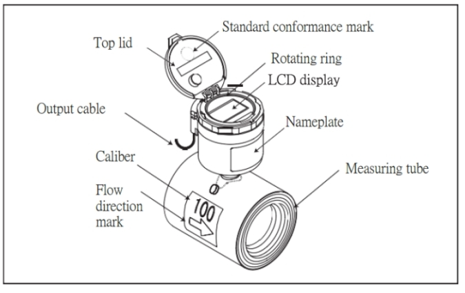
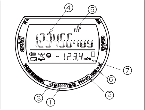
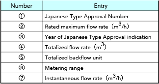
Description of Indicator
The meter is equipped with a liquid crystal display with backlight. The display can be reversed by grasping the rotating ring and turning it. Turn it in a direction that is easy to see depending on the installation position.
The display design changes when the indicator is reversed so that the forward and reverse directions are clearly visible.
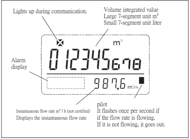
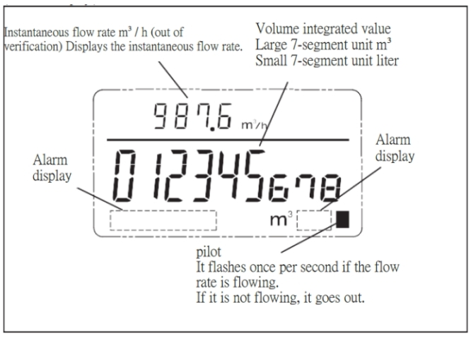
The backlight will turn on for approximately 30 seconds when the top cover is opened; after 30 seconds, the backlight will turn on again when the top cover is closed again. Cumulative total of 1 minute or less per day.
Precautions for Piping Installation Points
General precautions
For general precautions for water meters, refer to JIS B 8570-1 "Water meters and hot water meters.
For general precautions for electromagnetic flow meters, refer to JIS B 7554 "Electromagnetic Flow Meters".
Effects of external magnetic fields
Avoid installation near high current cables, motors, or transformers due to electromagnetic induction interference.
Installation in plastic piping
In the case of plastic piping, leakage current from pumps, etc. may ride on the measured fluid. Be sure to perform Class D grounding work.
Installation in piping subject to vibration
Do not install the instrument in a location where there is a lot of vibration.
Confirmation of flow direction
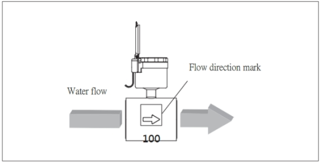
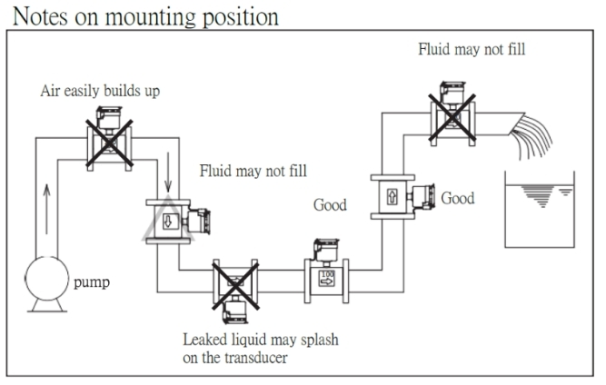
Ensuring full water supply
Electromagnetic flow meters cannot measure in pipes that are not full of water or in fluids that contain air bubbles. Therefore, please install the meter in a location where air bubbles do not accumulate.
Mixing of chemicals
If a chemical solution such as chlorine is injected near the primary side of the meter, the two liquids may not mix completely, resulting in electrochemical instability that may affect metering measurements. Injection of chemicals should be done at a distance on the secondary side of the meter.
Mixing of solids
We do not recommend using the meter under conditions where solids are mixed, because solids will settle at the bottom of the tube in slurry fluids where solids are mixed, and the flow will not be uniform.
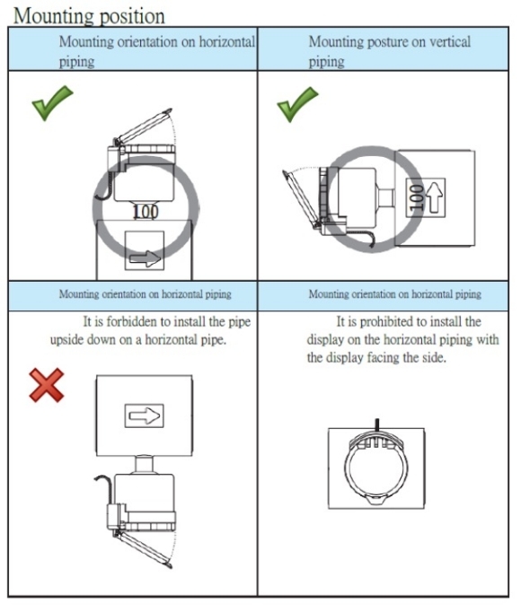
Precautions for fluids to be measured
The following fluids cannot be used.
・ When bubbles are large in volume and flow continuously
・ When a large amount of hard solids are contained
・ When containing insulating adherents such as oil
・ When magnetic materials such as iron powder are contained
・ When containing a surfactant
Operation check
Check for leaks
After installation, let the water flow and check for leaks at the connection between the meter and the flange. Note that the pressure applied to the meter is less than 1[MPa]. (main unit only)
Indicator status during normal operation
When water flows through the measuring tube portion of the meter and the inside of the measuring tube is full of water, the empty detection alarm disappears. The meter enters the flow measurement state.
When the meter is operating normally and fluid is flowing, the pilot mark blinks to indicate that fluid is flowing.
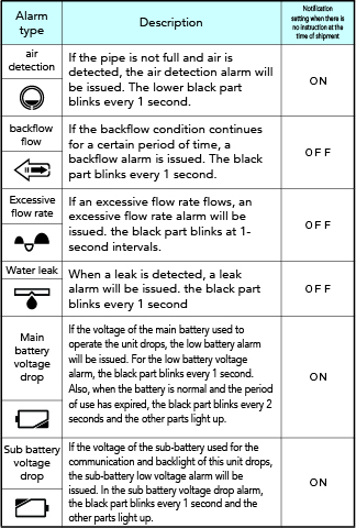
Alarm Indication and Factory Default Settings for Abnormal Operation
The meter displays the alarms shown in the table below when there is some kind of abnormality in the meter. The alarm settings for the meter are made at the time of order, and the meter is shipped after the settings have been made. The alarm conditions cannot be changed after shipment. If you have given us instructions for the alarm conditions, we will make the settings based on those instructions before shipment.
The alarm marked "ON" indicates that the meter is monitoring the condition. An alarm marked "OFF" is an alarm whose status is not monitored. When marked "OFF", the alarm will not be triggered.
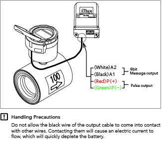
Connection to BPM Indicator and Other Peripheral Devices
The following figure shows how to connect the BPM indicator and the telegram system. Please refer to the respective instruction manuals for detailed information on how to use the BPM indicator and the telegram system.
Download catalog
Specifications, External drawing
[Tangential-flow-vane wheel type] Union connection type
![[Tangential-flow-vane wheel type] Union connection type](/asset/img/product/water/batterymeter/mgb12a/chart26.jpg)
- Common documents (PDF)
- Specifications (PDF)
-
No output
- All diameter sizes(50~200) (0.08MB)
- MGB12A-50 (0.08MB)
- MGB12A-65 (0.08MB)
- MGB12A-75 (0.08MB)
- MGB12A-100 (0.08MB)
- MGB12A-125 (0.08MB)
- MGB12A-150 (0.08MB)
- MGB12A-200 (0.08MB)
with output
- External view (PDF)
-
No output
- MGB12A-50 (0.08MB)
- MGB12A-65 (0.07MB)
- MGB12A-75 (0.07MB)
- MGB12A-100 (0.08MB)
- MGB12A-125 (0.08MB)
- MGB12A-150 (0.08MB)
- MGB12A-200 (0.08MB)
with output

