- 13mm
- 20mm
- 25mm
- 30mm
- 40mm
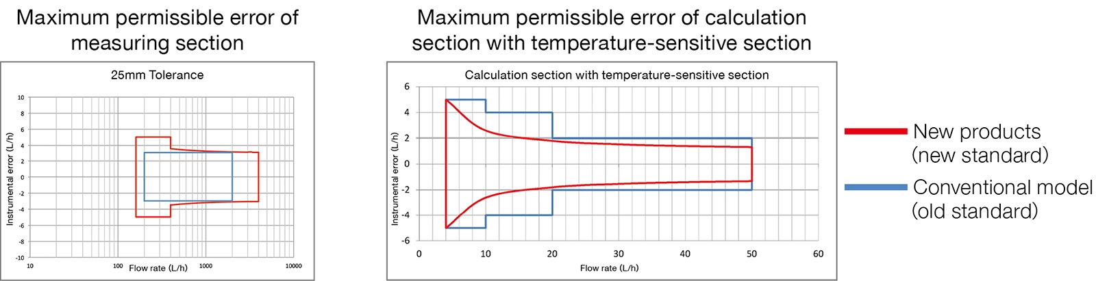
- Expanded measuring range
2.5 times greater than conventional models (our model KSE)
Minimum to maximum range is 1:25. - Visibility of the LCD display has been improved.
Larger letters on the totalized value make it easier to read than the conventional type, and a variety of contents are displayed for easier management. - The maximum allowable operating pressure has been increased to 1.6 MPa.
- The structure of the measuring section has been changed to reduce weight.
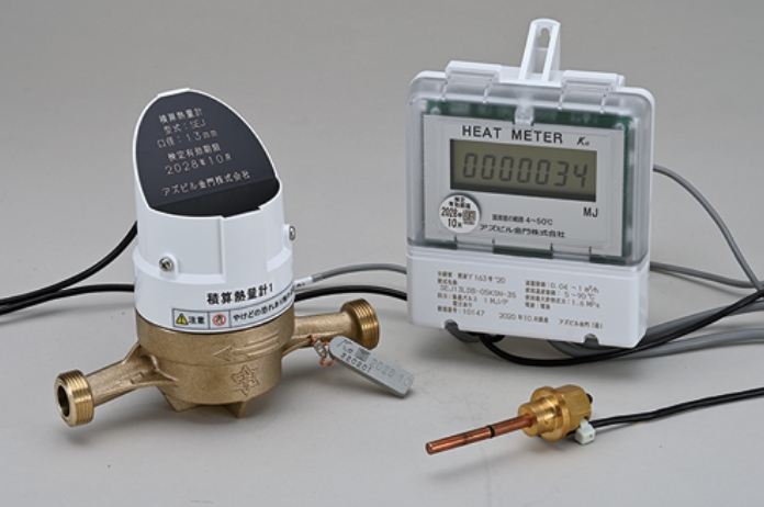
A total calorimeter is a measuring instrument that measures the amount of heat consumed by a heat exchanger for air conditioning, etc. in a building (building, housing complex, etc.).
Hot or cold water supplied from a heat source (boiler, etc.) is exchanged in a heat exchanger for air conditioning, hot water supply, etc., and the amount of heat (thermal energy) consumed there is displayed.
The calorific value is calculated based on the temperature difference between the send and return sides and the passage volume measured by a flow meter.
Calorific value = Passage volume of cold and hot water × Temperature difference between feed and return sides × Calorific value conversion coefficient
The diameter of 40 mm or less is a specified measuring instrument under the Measurement Law.
The validity period of verification is 8 years.
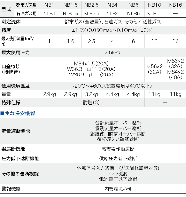
Compliance with the new standards of the Measurement Law
(for measuring instruments with a bore size of 40 mm or less)
Due to the revision of the Measurement Law, all products manufactured and sold will be changed to comply with the new standards from September 2017.
Click to enlarge
New product lineup (model SEJ)
Click to enlarge
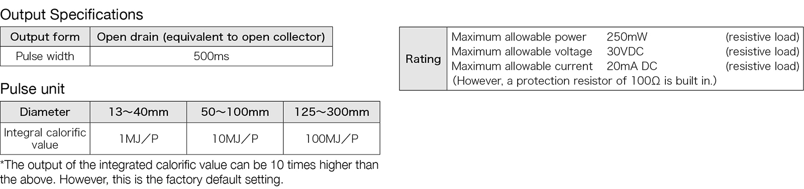
Output Signal (Option)
Pulse output and telegram communication can be used for various types of remote meter reading.
Pulse output
Click to enlarge
Telegram communication: 8-bit telegram communication
This page contains only excerpts of important information regarding the installation of this product.
Please be sure to refer to the instruction manual before mounting and installing this product.
This product is designed for indoor installation. Do not install the product in the following places
- Places subject to vibration or water hammer, piping
- Locations where it is difficult to read the meter or where it is exposed to direct sunlight
- Places submerged, flooded, or exposed to water, places with poor ventilation at all times, or places where moisture causes condensation
- Locations where equipment prone to noise surges is located, or where strong electric or magnetic fields are applied, such as directly under high-voltage lines
- Places where oil (kerosene, fuel oil, etc.), dust, or corrosive gases are present.
- Where the ambient temperature exceeds 60°C (140°F) or falls below -10°C (-40°F).
- Where the ambient humidity exceeds 90%RH
- Locations where mounting and dismounting are difficult or where there is no space for maintenance and inspection
- Wiring work must be performed in compliance with the Electrical Equipment Technical Standards, internal wiring regulations, the Electrician Law, and the Fire Service Law.
- Do not cut or extend the flow sensor or temperature sensor cables.
- Separate the flow sensor and temperature sensor cables from the power and power lines of other equipment.
- Install the temperature sensor on the piping with the feed side on the heat load inlet side and the return side on the heat load outlet side as indicated by the label on the signal line.
- For the AC type, insert the power plug into the outlet after all installation work is completed.
- Match the serial numbers of the calculation unit and temperature sensor.
The performance and durability of the totalizing calorimeter will vary depending on whether the piping is good or bad. Pay attention to the following points when installing the unit.
If the flow of cold and hot water can be stopped, refer to Piping Example 1; if not, refer to Piping Example 2.
- Do not install the volumetric measuring unit in a location where it may freeze.
- Do not install in a location where air remains in the volume measuring section.
- Install the volumetric measuring unit on the return side.
- Install the volumetric measuring section on a level surface. The electromagnetic type can be installed in vertical piping.
- Install the volumetric measuring section in a location where water pressure fluctuation is minimal.
- When welding pipes, remove the volume measuring section.
- Remove the volumetric measuring section when flushing the inside of the piping.
- Install maintenance valves upstream and downstream of the temperature sensor on the feed side.
- Install a straight pipe at least 5 times the bore diameter upstream of the volumetric measuring section and a strainer (recommended 40 mesh) upstream of the strainer.
- Install maintenance valves upstream of the strainer and downstream of the temperature sensor on the return side, and install a drain valve to drain the cold and hot water between the strainer and the sensor.
- Provide a bypass throughout from the strainer to the return side temperature sensor and install a valve on the bypass.
- If water meters, etc., are installed in the same pipe shaft, install the volumetric measuring section at a higher position than the water meters, etc., so that water will not splash on the flow sensor section when the water meters, etc., are replaced.
- The temperature sensor and the volumetric meter should be installed near the heat load.
- The temperature sensor insertion port of the temperature-sensing section should be facing upward.
- Attach a heat insulator to the volume measuring section (metal part).
- Do not attach a heat insulator to the upper part (plastic case) of the volumetric measuring unit.
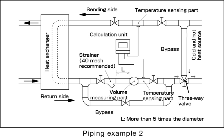
Example of piping
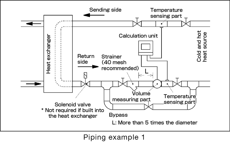
≪Points for piping example 1.≫
- ・If there is an output from the control equipment of the heat exchanger to the solenoid valve that controls the flow of chilled/heated water, install a solenoid valve downstream of the heat exchanger. This is not necessary if the solenoid valve is built into the heat exchanger.
≪Points for piping example 2.≫
- ・Install a bypass on the cold/heat heat source side of the entire piping and a three-way valve in the section connecting to the return side.